A double crank model to down load and make. If you are a member you can download the parts at the end of this blog post. Non-members can download the parts for a small fee in a couple of days.
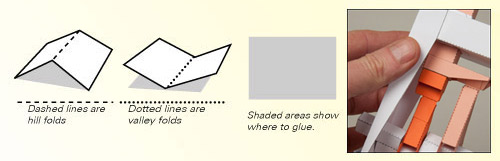
Print out the parts onto thin card (230 micron/230 gsm) Score along the dotted lines and cut out the solid black lines. Grey areas show where to glue.
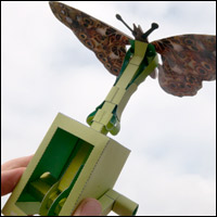
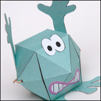
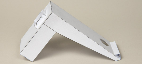
 This animation shows the completed model in action. The single crank shaft drives two separate push rods one inside the other. The motion of the outer push rod follows ninety degrees behind the motion of the inner pushrod resulting in this interesting fluid movement. It should be a good starting point for a number of different paper animations!
So, parts and glue (PVA – white school glue) at the ready. Time to start building!
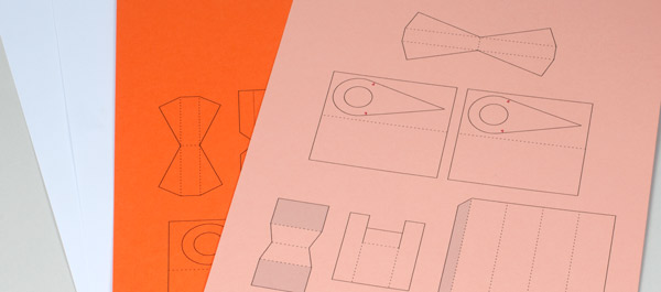
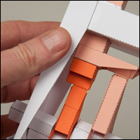
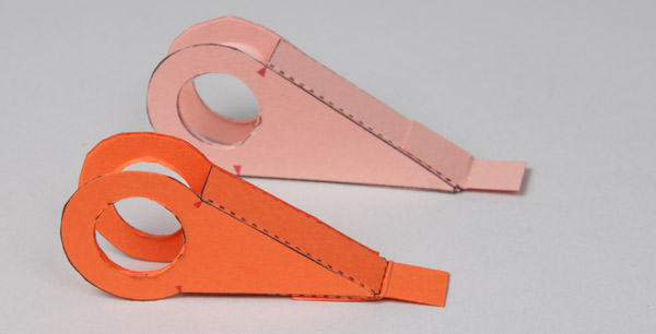
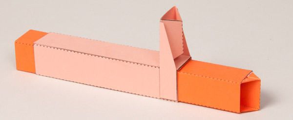
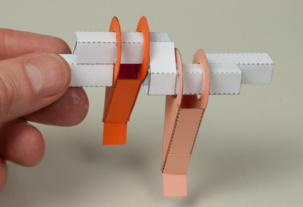
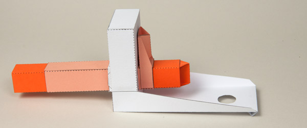
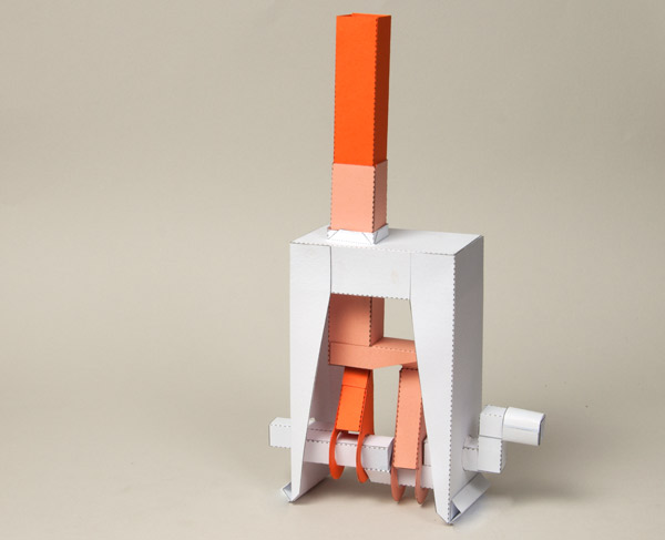
The third and forth pages of the file contain the parts of the inner and outer push rods respectively. I printed them onto different coloured card to make it clear which part did what in the final model. I used orange for outer and pink for inner.
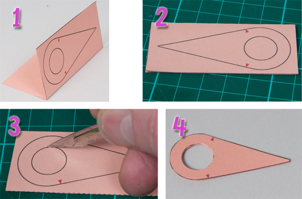
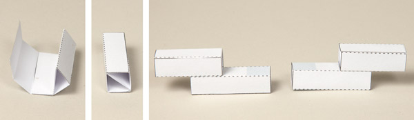
There are four linkage sides to make up. For each one follow these steps.
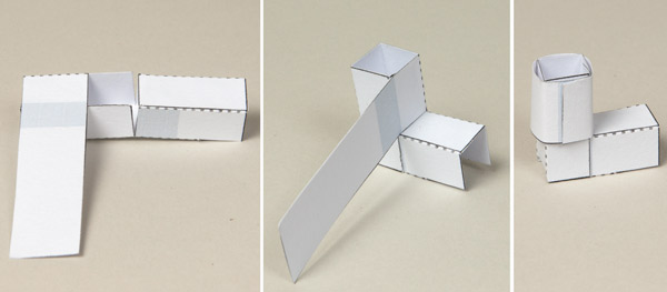
1) Fold the card in half and glue it down to make it double thickness card.
2) Set it to one side until the glue is completely dry. If you try and cut it while the glue is still wet there is a risk of ripping the card.
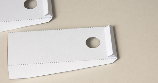
3) Once dry, use a sharp knife to cut out the centre hole.
4) Complete the part by cutting round the outside.
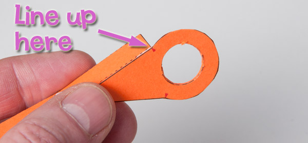
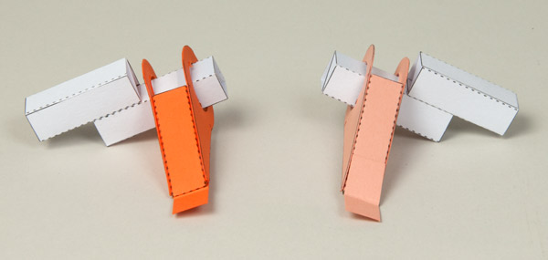
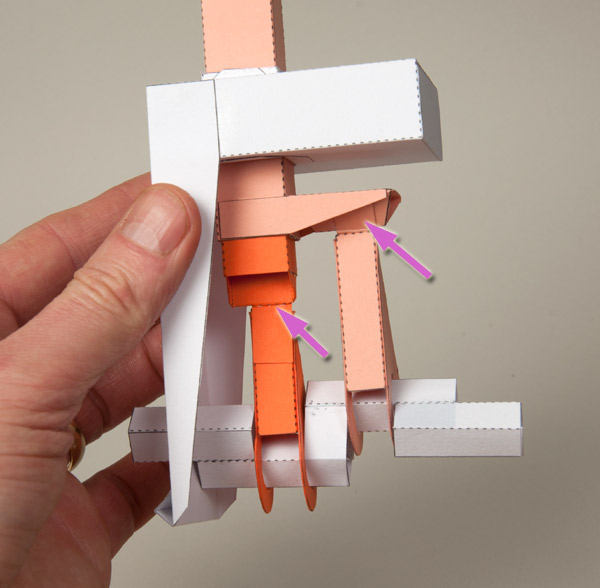
Assemble the linkages by gluing on the face parts being careful to line up the end with the small arrow on the side (arrowed above).
Complete the linkage by gluing on the other side and gluing the tab to the end.
Fold round and glue together the outer push rod tube.
Glue the outer push rod side into place carefully lining it up the edges with the top of the tube.
Fold round and glue together the inner push rod.
Fold the inner push rod end in half as shown.
Apply glue to the sides of the push rod end and thread it into the inner push rod so that it is lined up as shown.
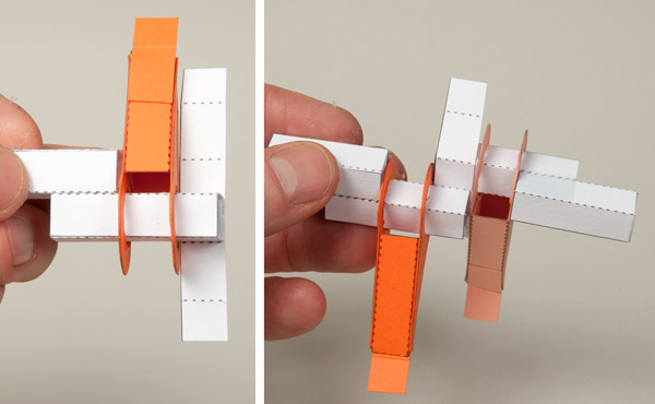
Thread the inner push rod into the outer push rod.
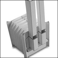
Assemble the two halves of the crank as shown above. The diagonal piece in the tube gives the tube rigidity. Each crank half consists of a long piece and a short piece. Glue the two crank parts together using the grey areas for alignment.
Thread the linkages onto longer sections of the crank halves as shown above.
Glue one of the cranks to the central section of crank joiner strip lining the crank up between the small arrows and the dotted line on the strip.
Fit the other crank half to the back of the top half of the crank joiner centre section. Note that the second crank half is rotated ninety degrees.
Fold the remaining flaps on the crank joiner round and glue them to the crank halves making triangular sections.
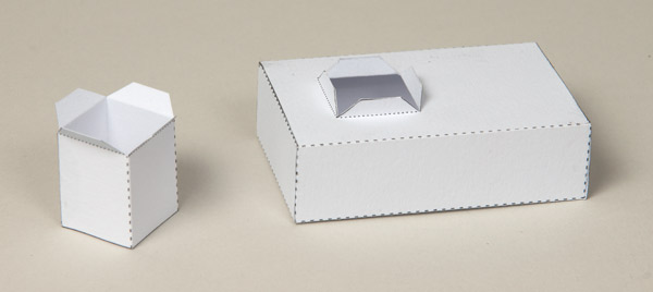
Glue together the box top and slider tube.
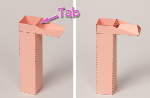
Thread the slider tube into the box and glue down the tabs front and back.
Fold the tabs round on the sides to make triangular sections as shown.
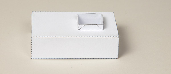
Carefully glue the side to the box top. Notice which way up the box top is on the photograph above.
Thread the push rods up through the slider tube.
With the shorter linkage lined up under the inner push rod, fit the crank end into the hole in the box side.
Glue the two tabs in the ends of the linkages into place on the inner and outer push rods.
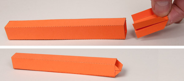
Assemble the handle in three stages. Fold the two halves up to make square section tubes.
Fold and glue one half inside the other.
Roll round the long tab and glue it down.
Complete the model by gluing on the second side carefully and accurately then adding the handle.
Once the glue is dry, turn the handle and watch how the intriguing motion works. Use this as a free standing interesting mechanism or as the starting point for your own designs. Let me know how you get on!