Essential Mechanisms™
Mesh Gear Type 2
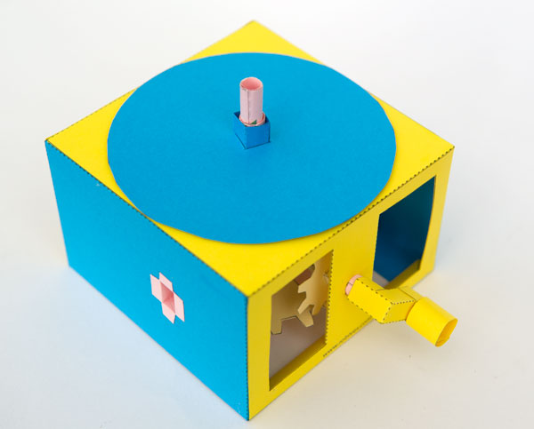
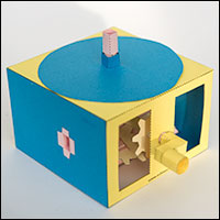
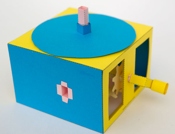
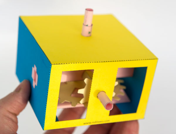
Turn the handle on the side of the box and the large disk on the top of the box revolves. The type 2 mechanism features a fixed tube to which stationary objects can be attached making it possible, for example, to make a model featuring a dog chasing round a stationary tree.
Paid subscribers can download the parts file from the link for free. Non-members can join in the fun for just £2.50.
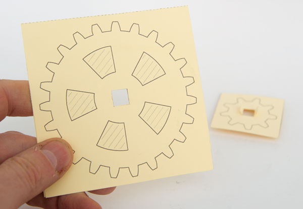
Once you have downloaded the file, print the parts out onto thin card (230 micron 67lb) I have used coloured card in these instructions to create a colourful model. You can use coloured, white or patterned card for yours.
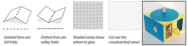
Score along the dotted and dashed lines and cut out the holes before carefully cutting out the parts.
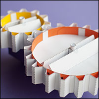
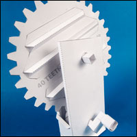
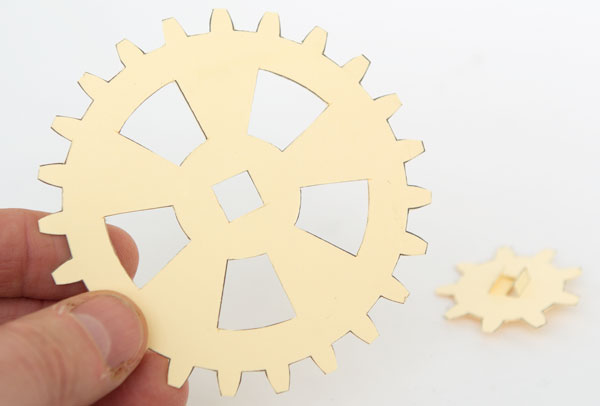
Fold the gears in half and glue them down to make double thickness card
Once the glue is dry carefully cut them out.
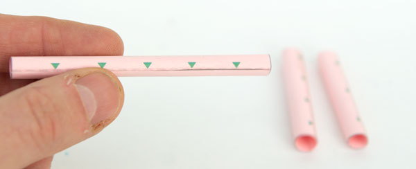
Roll up and glue the three axle tubes lining up their edges with the points of the arrows.
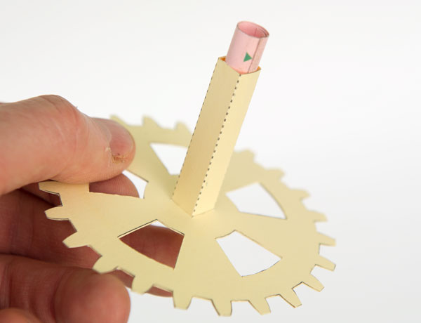
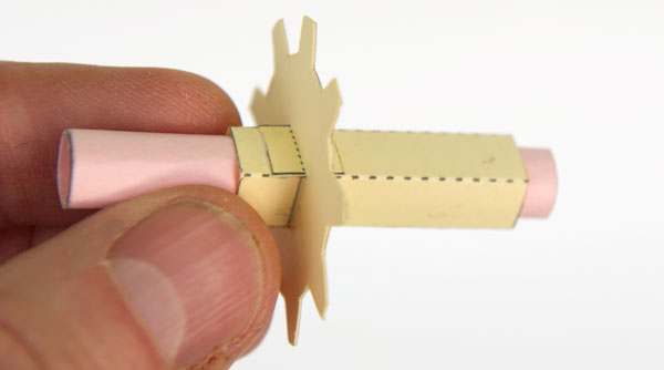
Glue the gear axle tube to the gear then glue the 9mm diameter tube into place inside the square tube. Line up the end of the axle tube with the end of the square tube.
Glue the pinion gear to the pinion gear axle lining it up with the grey line.
Thread the 8mm tube into place lining up the square tube between the two grey lines and glue it into position.
Fold round and glue together the base. Don’t glue the ends yet.
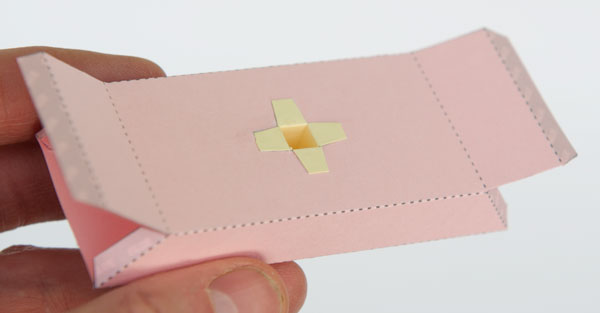
Glue the spacer into place as shown reaching inside to press the tabs down firmly.
Glue down the base ends.
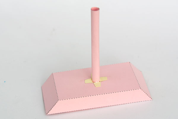
Fit the 7mm tube into position.
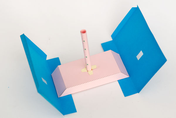
Glue the box sides to the base using the small arrows for alignment.
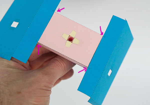
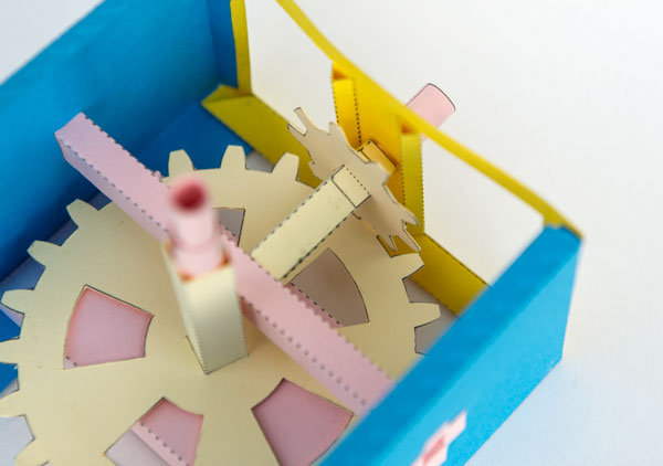
Top view of the base with the sides glued on.
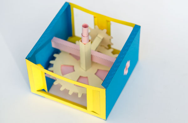
Glue one edge of the front to one of the side edges closest to the rectangular hole in the box side.
Glue the other side of the front into place.
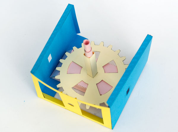
Drop the large gear into place onto the vertical shaft. It should be free to turn.
Fold up and make the pinion support.
Glue it into place between the two sides with the hole facing towards the front.
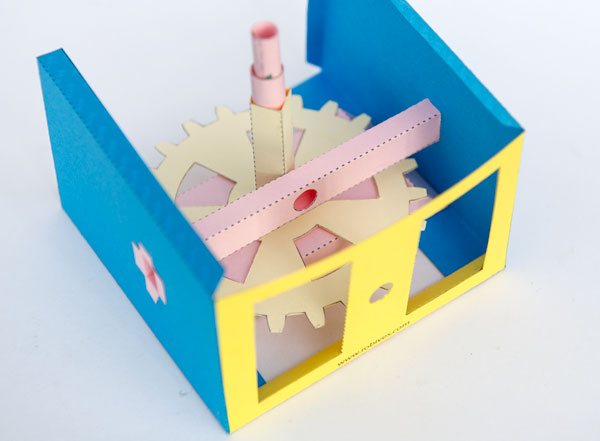
Fit the pinion into place between the pinion support and the box front as shown.
Glue the box back into position.
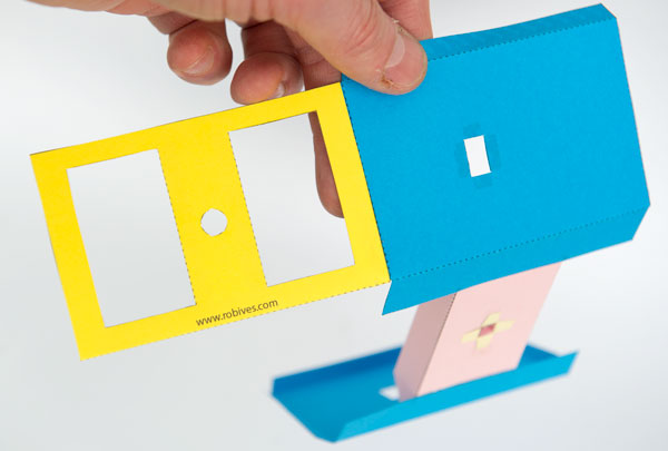
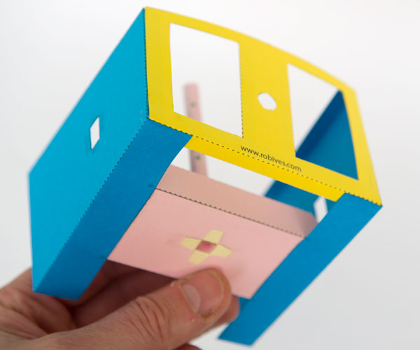
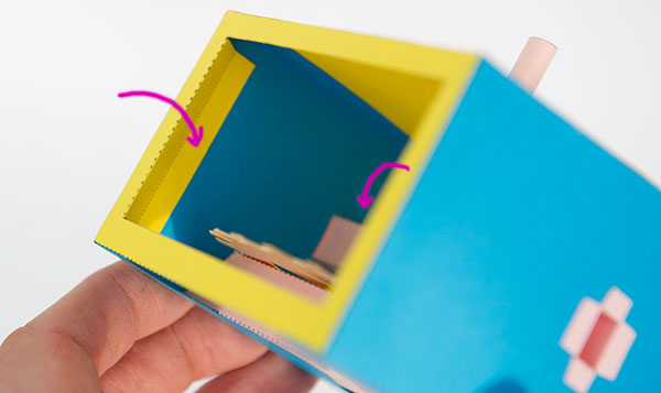
Thread the box top down over the vertical shafts and glue it down to the box.
Fold in and glue down the tabs at the back.
Assemble the handle in three steps.
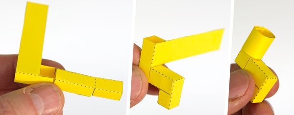
Glue the handle to the pinion shaft.
Thread the disk inner into the disk and glue it down.
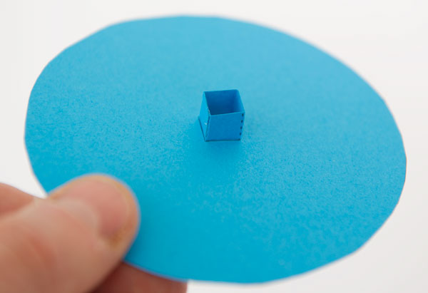
Glue the disk to the outer rotating vertical shaft.
If you choose you can add the square section piece to the inner tube as a place to attaching model parts in your design. This part will be stationary.

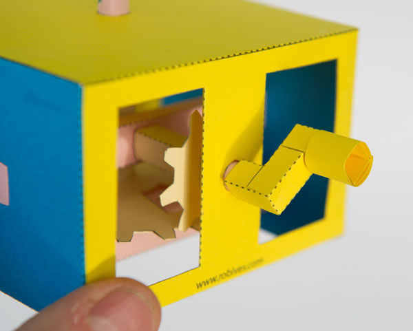
Turn the handle and the disk rotates. The gear reduction is roughly 2.5:1
Use this an experiment in pure mechanism or as the starting point for your own designs.