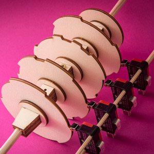
Rotors and micro-switches. These will make up the timeline for a forth-coming project. As the rotor turns the switches turn on and off controlling a variety of solenoids and electric motors to bring an automata to life.
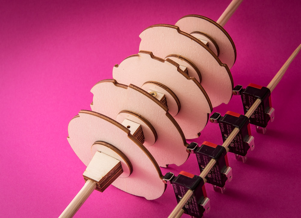
To tell the full story I need the rotor to take ten seconds to make one complete revolution.
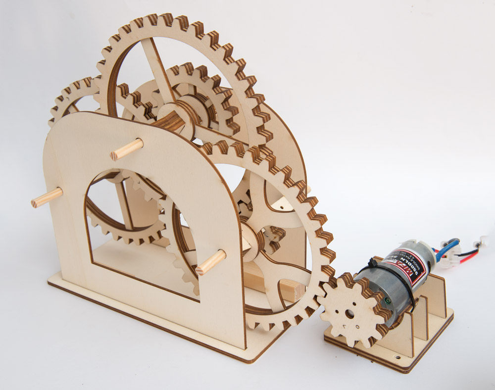
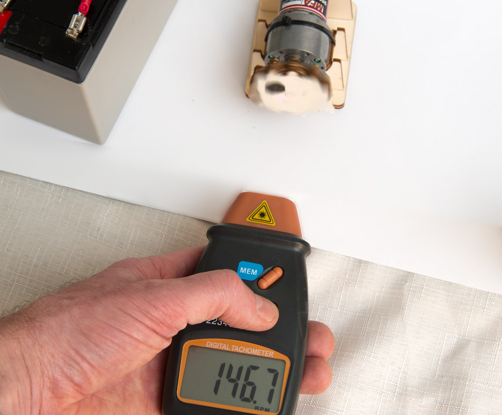
I have a drive motor which, according to my rpm meter, turns at roughly 145rpm plus or minus a few rpm.
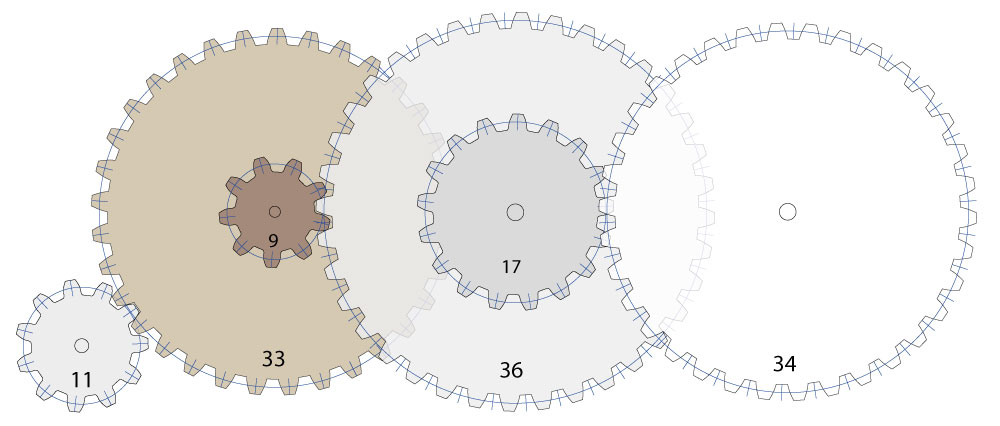
I reckon that a 24:1 speed reduction should do the job. Working left to right this gear train has reductions of 4:1, 3:1 and 2:1. When multiplied together this give an output speed 6rpm. Perfect!
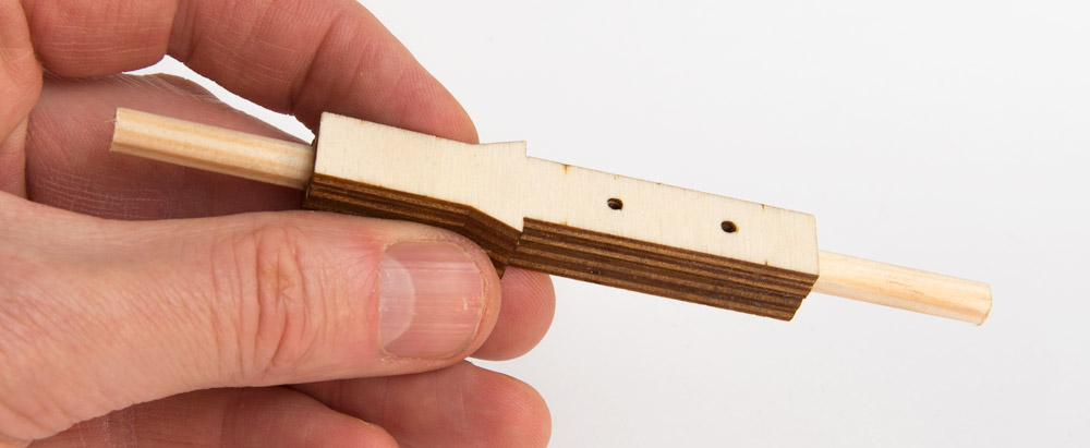
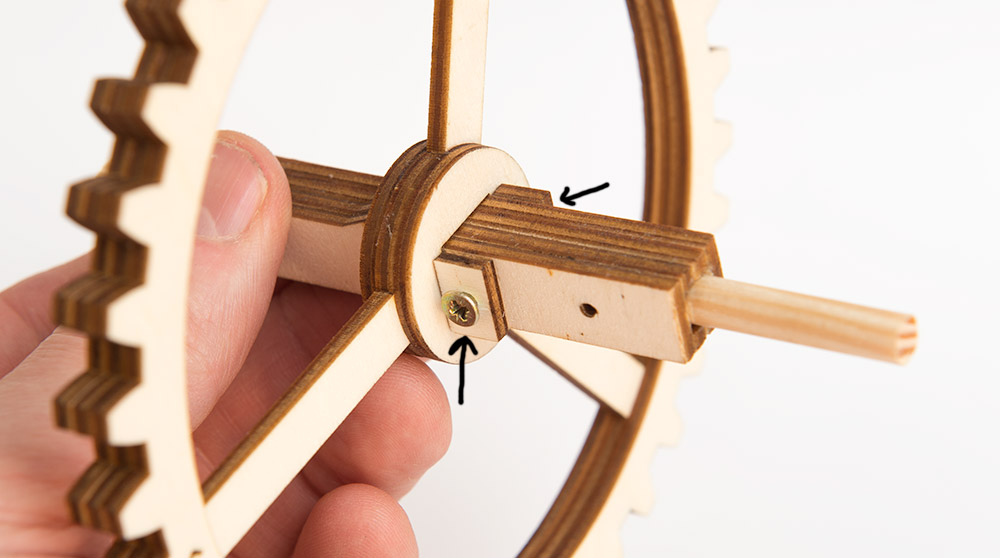
I’m trying out a new axle design with the laser cut gears. Four layers making up a 12mm square section with a hole at each end for a 6mm diameter dowel. 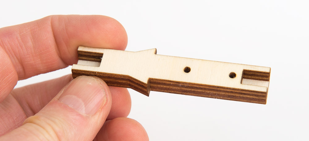
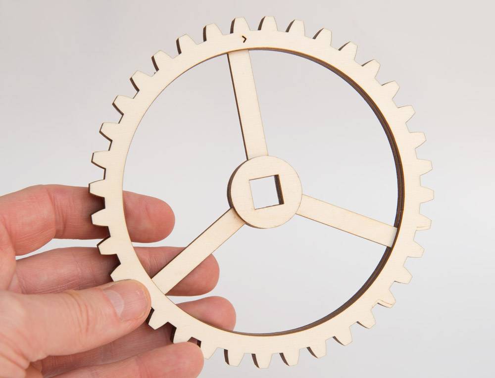
I designed the gears using the software from woodgears.ca I import the outline into Illustrator to add spokes and axle hole then cut out the three layers with a laser cutter from 3mm thick plywood.
I then slipped the gear onto the axle and fixed it into place with these two blocks.
A couple of advantages of the new square based axles:
Because of the triangular ledges the gear is naturally held square to the axle.
The screw in blocks allow the gears to be fixed into place without glue so they can be removed at a later stage.
 The second gear fits on after the first and again I secured it with screw on blocks.
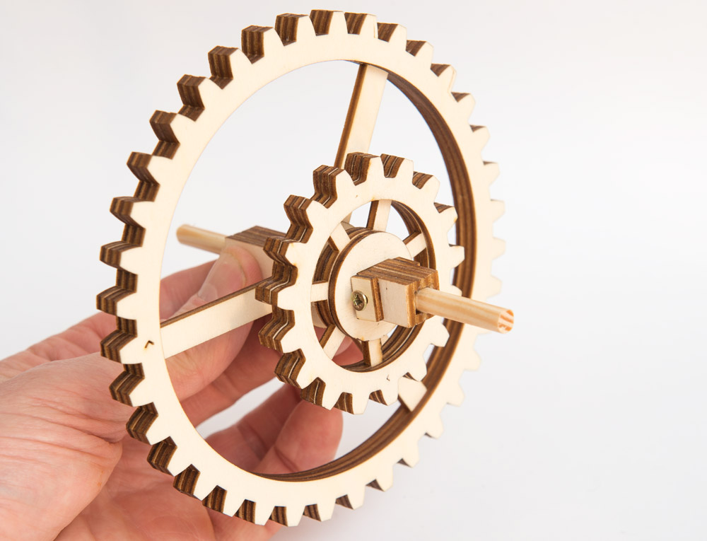
I assemble all three gears and make a back plate with suitable holes to align them.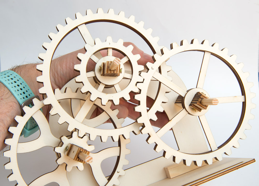
Finally, a second side plate and a base complete the gear train.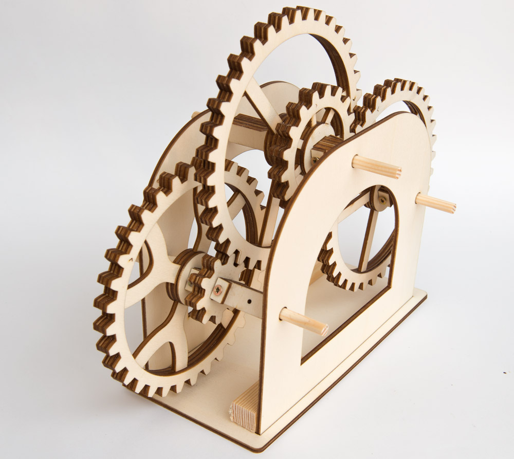
With the 11 tooth drive gear in place the output shaft, on the left, turns at roughly once per 10 seconds!