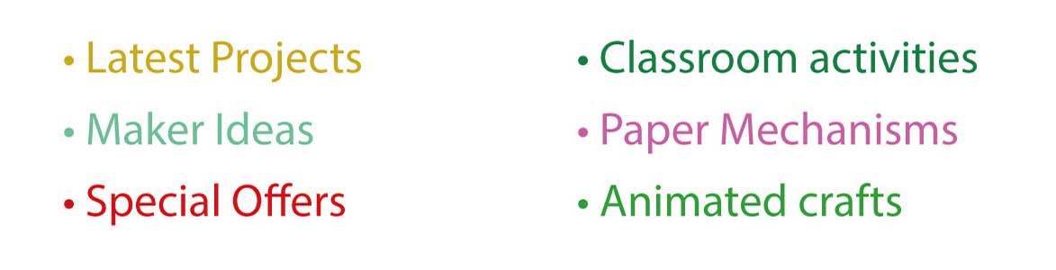
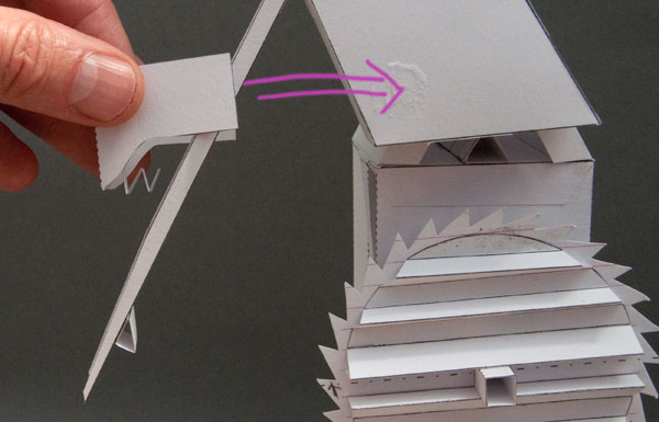
More progress on the escapement model. I've been attaching the palette today, these are the parts that touch the tooth of the escapement wheel. In this model they are the connection between the pendulum (round the back – you can't see it) and the wheel.
There will be two palettes each joined to the pendulum via a long connecting rod. One will make the pendulume swing one way – the other the other. Tick – Tock. I'm adding them one at a time. The connecting rod needs to be positioned so that it lines up with the wheel as the pendulum swings past the centre line. To add complications, it needs to be able to swing back and forth but sit naturally in the centre of its range.
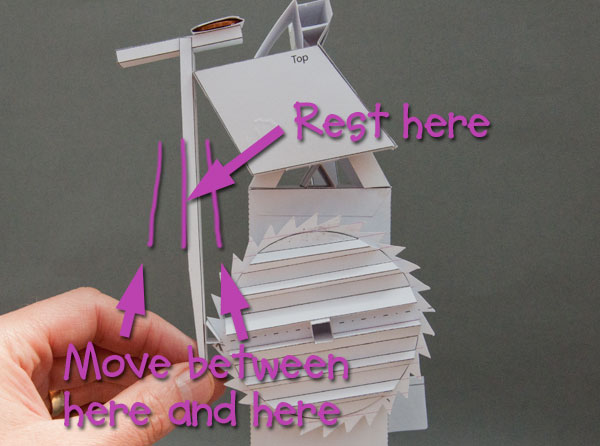
In clocks made from more traditional materials that would be done with a spring. In this paper model I've used a zig-zag of paper as a spring.
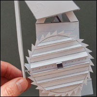
The spring sits inside a cover and holds the connecting rod central whilst the coin to the left of the rod returns it if it swings the other way.
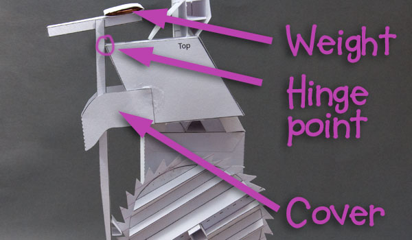
Above is the finished assembly.
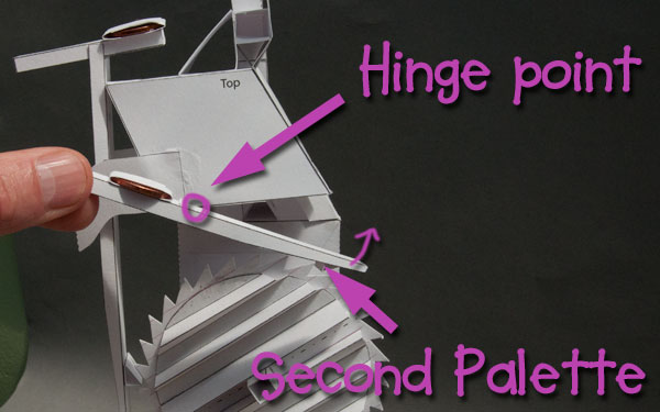
This bit has had me stumped for a while. How do I fit in the second palette? There simply isn't room. It need to go where it is in the picture but there is no space. I think I'm going to have to bite the bullet and fit a second wheel for it to drive.
I've been planning to do a YouTube video following the delvelopment of a model from start to finish showing the design process, the failures, the tears, the despair… finishing with a completed project. I could use a mix of film and animation to show how its all done, I think it could be quite interesting. This would have been a good project to have filmed as it has all sorts of interesting problems to be solved. Too late now though. Would you be interesting in such a video if I put one together?