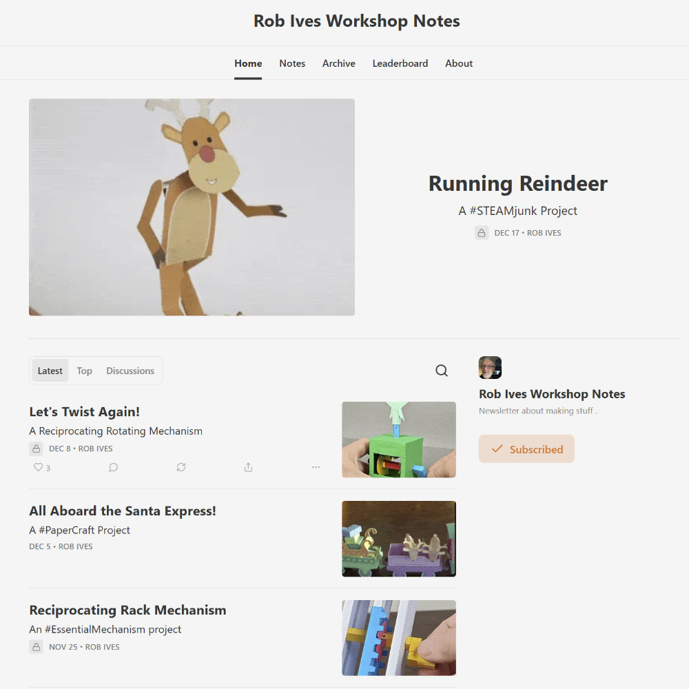
The blog has moved to Workshop Notes on Substack… workshopnotes.robives.com
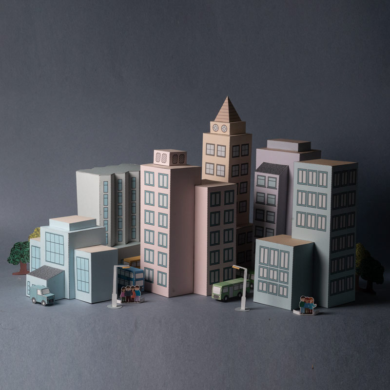
Paper City with Skyscapers. Download and make this new project
Find out more and order your own here!
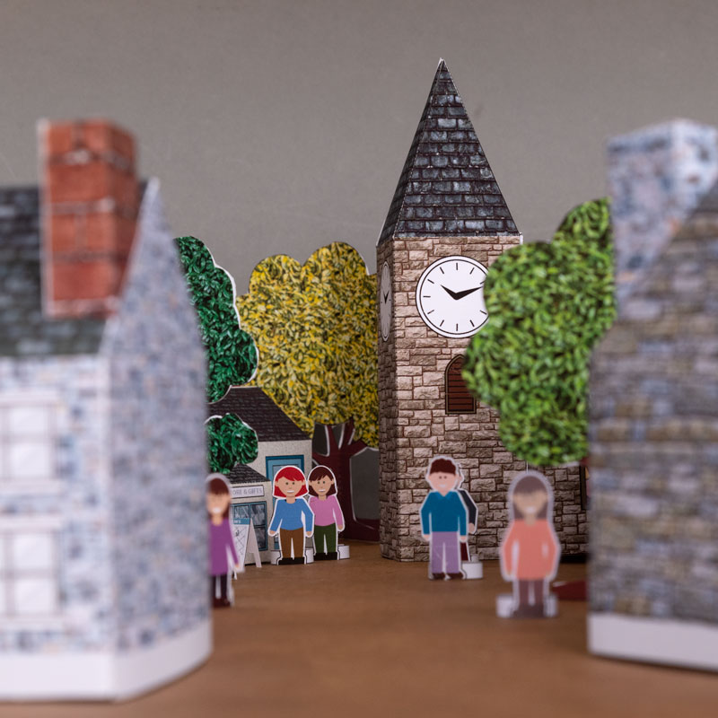
Check out the downloadable Paper Village that I have created
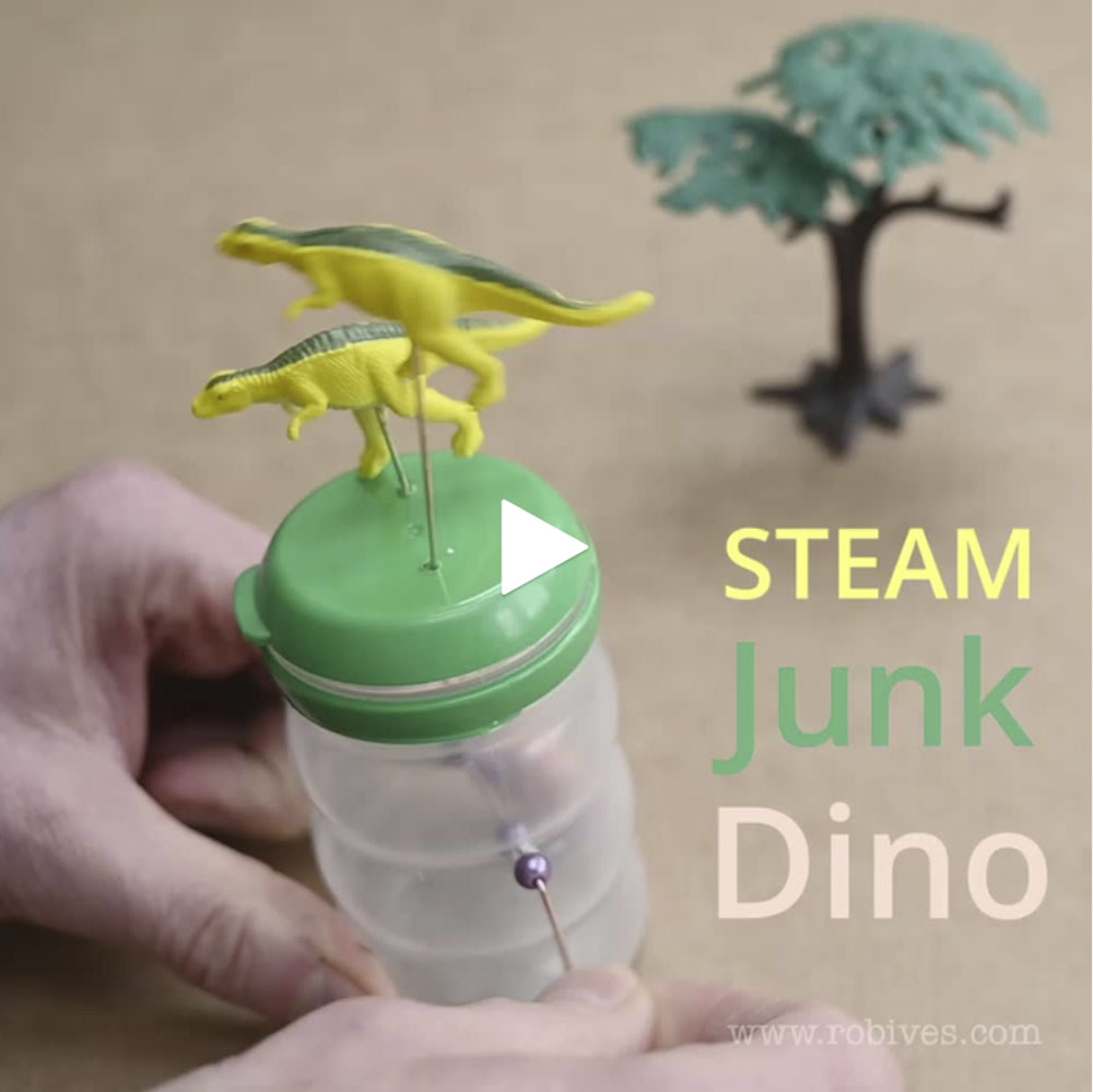
#STEAMJunk Dinosaurs. I bought a tube of mini-dinosaurs! Time to
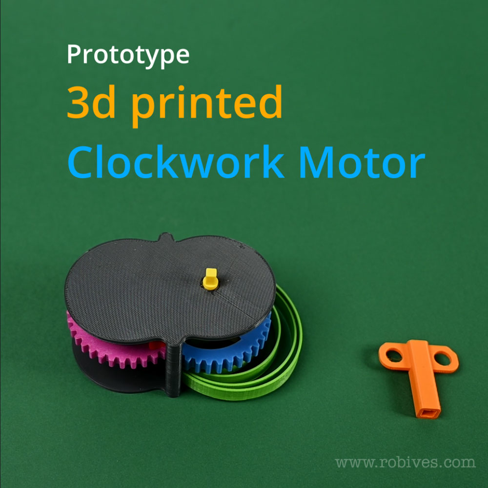
Check out this YouTube video on latest developments in my
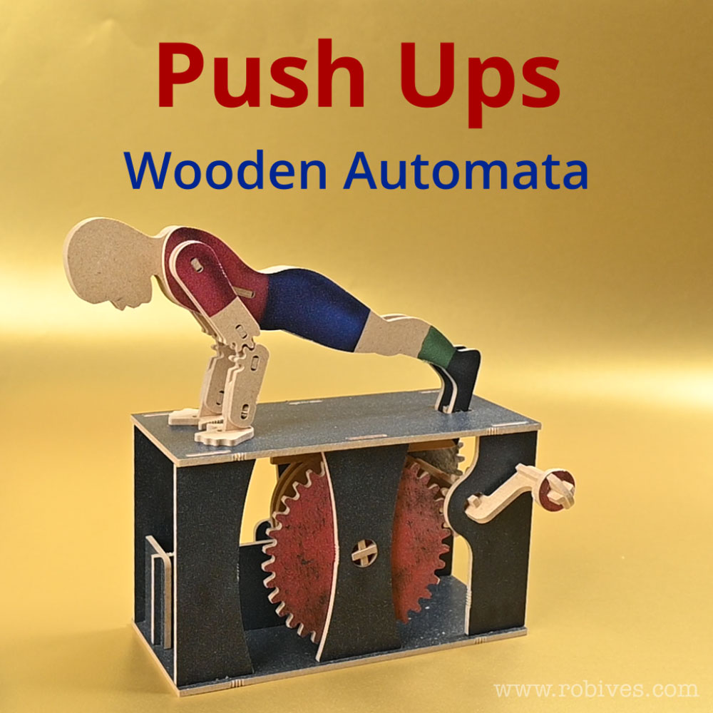
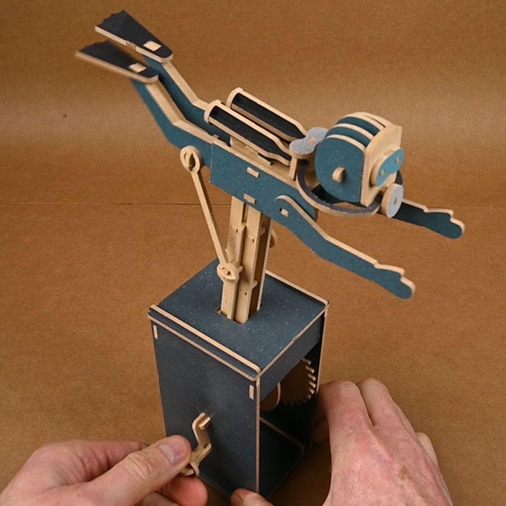
New! First video of my new range of wooden automata!
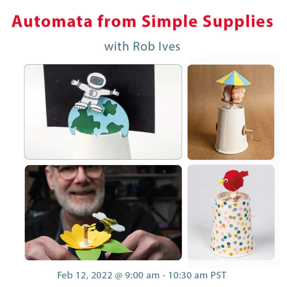
Join me for an online hands-on workshop on how to
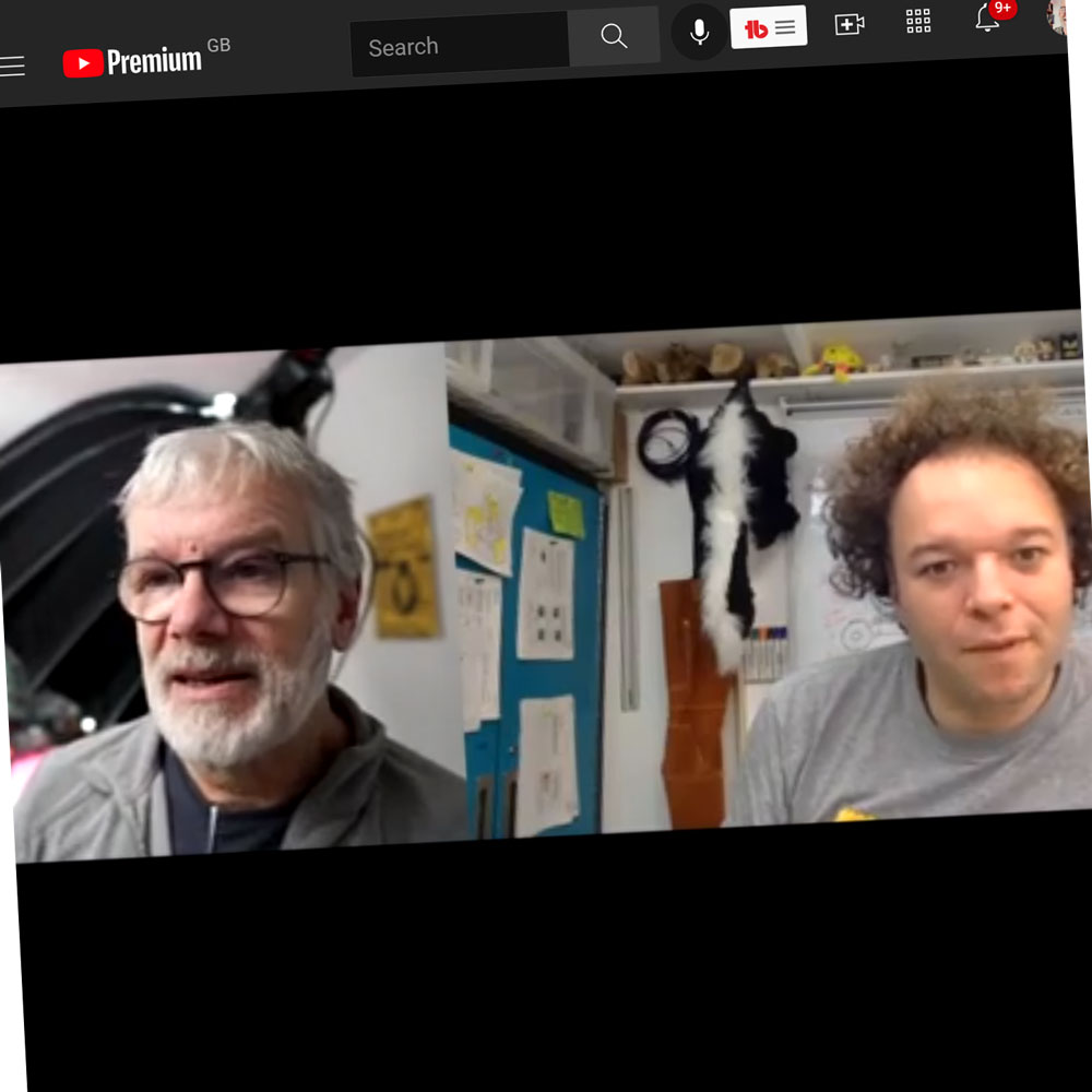
I had a fun chat with Maker/Product Design Engineer Jude
I was delighted to return from my recent travels to
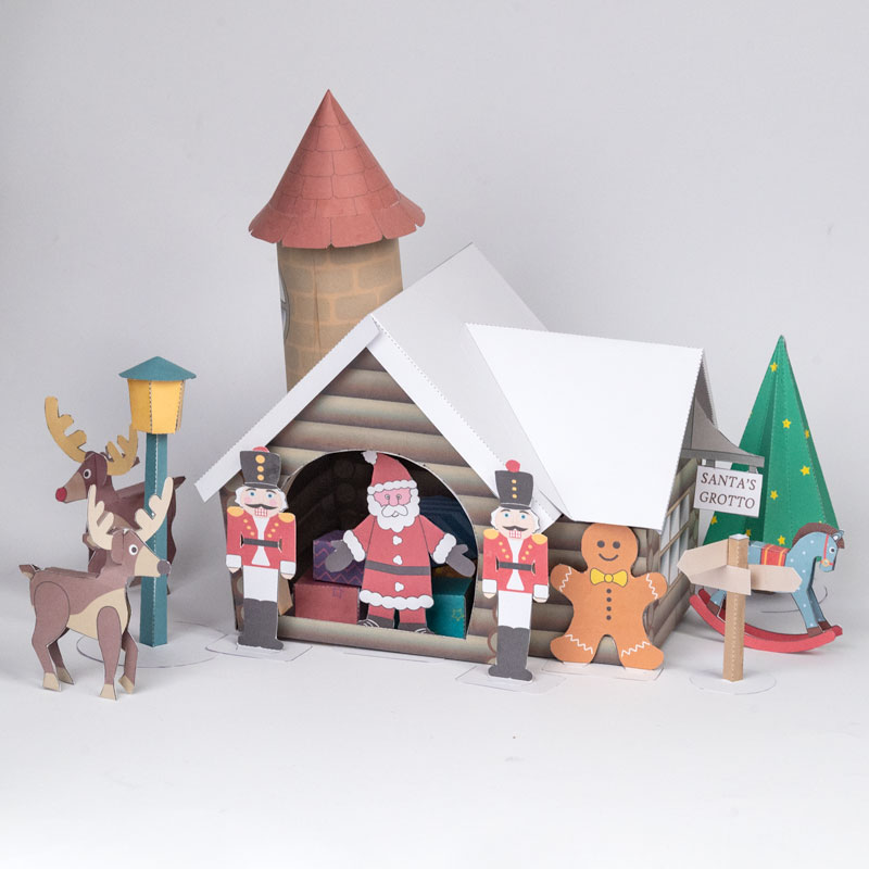
New on the Brother Creative Center, check out the Santa’s
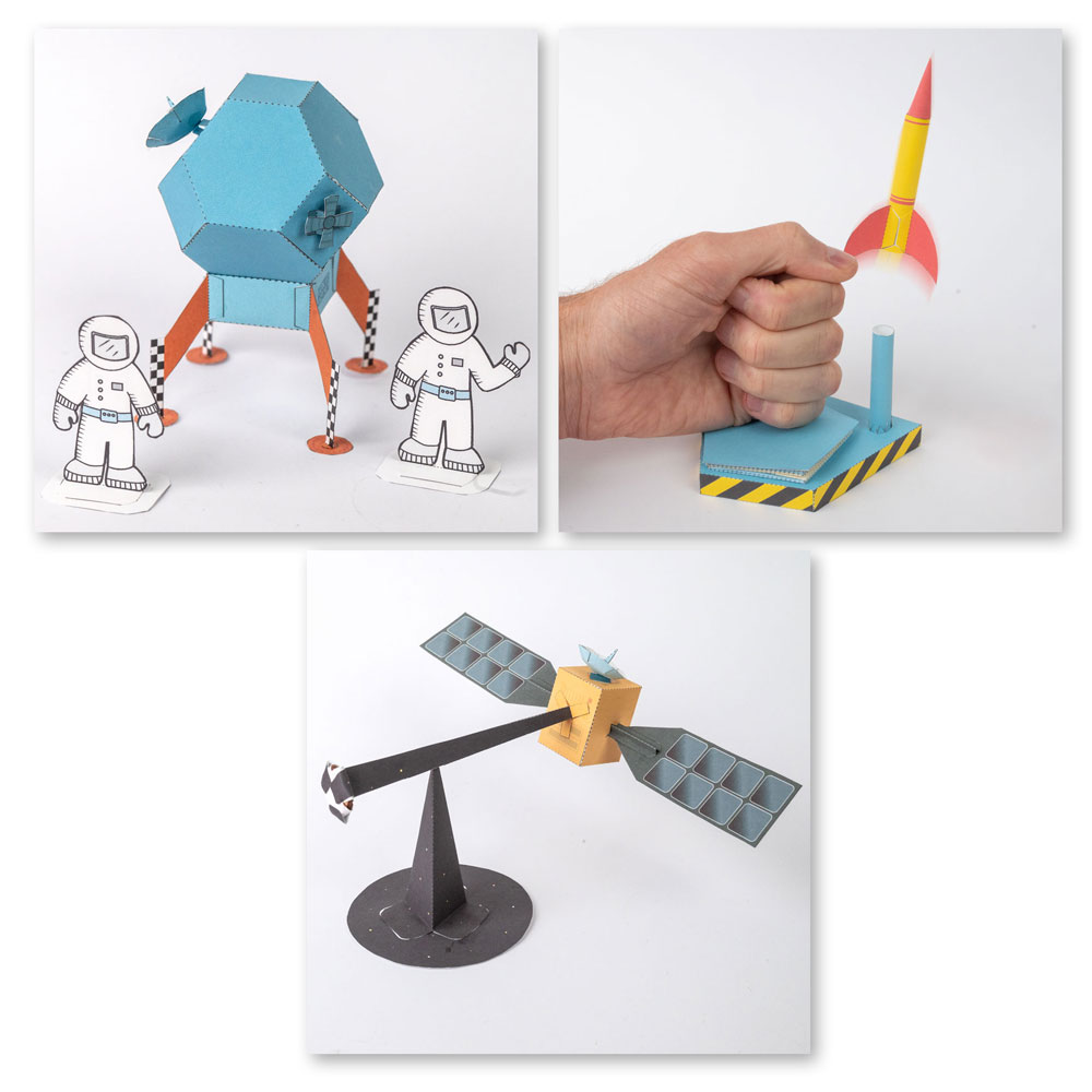
Check out this new range of Space Themed paper projects