
 Invented by James Watt, the Watt Linkage is a simple way of creating almost straight line motion. You can find out more details about the linkage here. If you are a member you can download the parts and make your own working Watt Linkage mechanism to see it in action first hand!
Print out the parts onto thin card (230 micron/ 230 gsm) Score along the dotted lines and cut out the holes before cutting out the parts.
Dotted lines are valley folds, dashed lines are hill folds, solid black lines show where to cut. Grey areas are used to show where to glue.
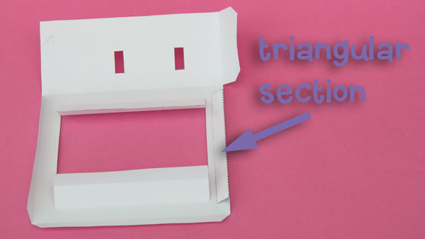
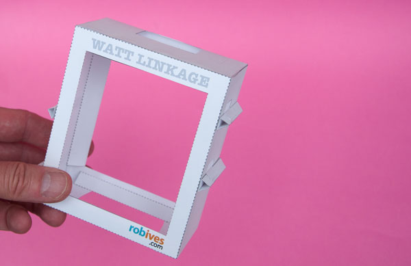
Glue up the triangular sections on the two box pieces.
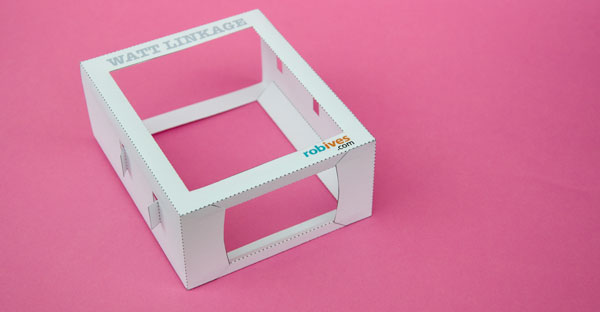
Glue the two box halves together as shown.
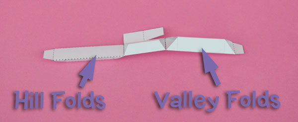
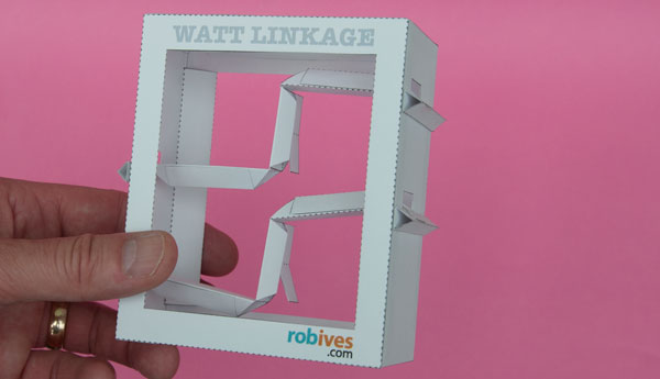
Fold up and glue the two linkage parts. Note the hill and valley fold markings so that you can see where to fold up and where down.

Glue together the four triangular side stiffeners.

Glue the side stiffeners to the grey areas on the side of the box then fold down and glue the flaps to the side stiffeners.
Glue the lid into place.
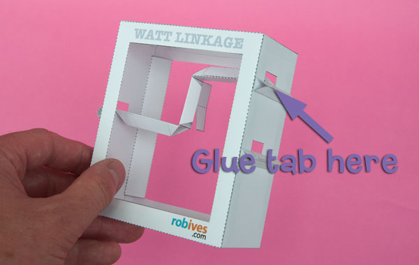
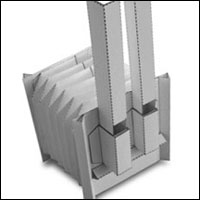
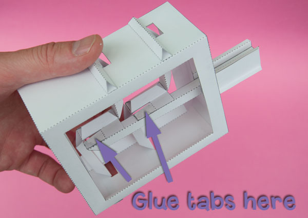
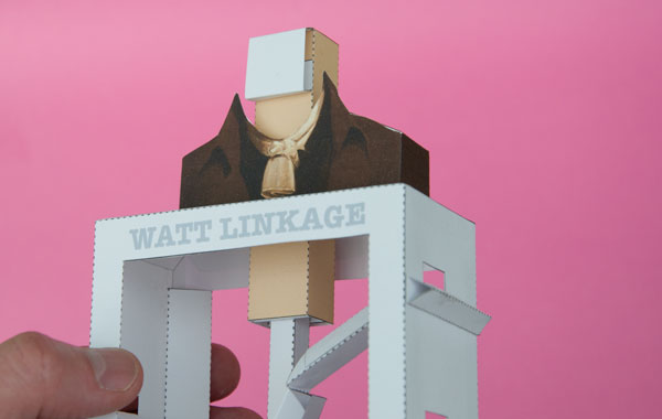
Fit the linkages into place and glue the tabs to the side stiffeners. Use the picture above to ensure that the parts are lined up the right way.
Glue the second linkage into place.
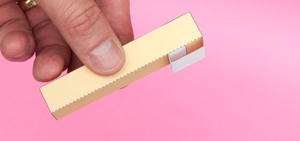
Fold up the rod and glue on the rod ends using the grey areas for alignment.
Glue the rod to the tabs on the centre of the linkages. Use the grey areas for alignment.
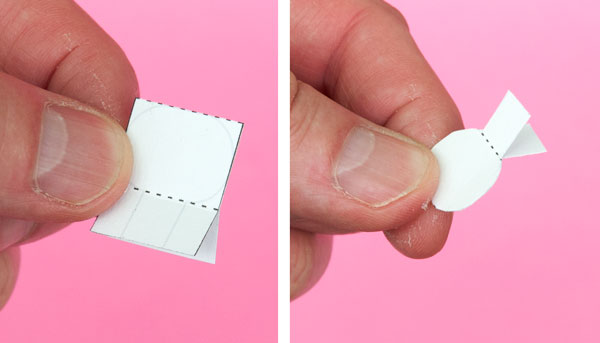
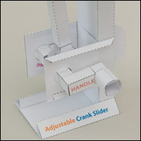
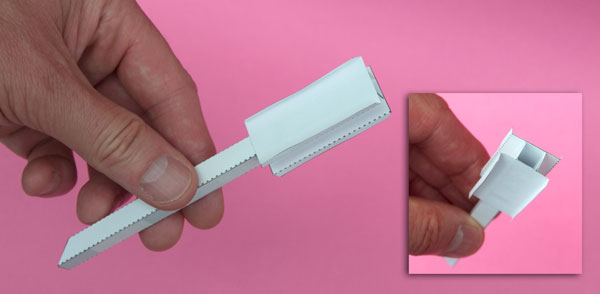
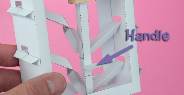
Assemble the handle as shown above.
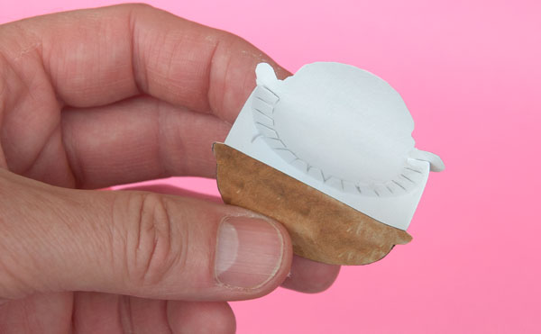
Glue together the three parts of James Watt’s head.
Assemble the neck tube as shown.
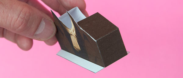
Fold round and glue together the shoulders.
Glue the shoulders to the box top using the edge of the hole and the grey rectangle for alignment.
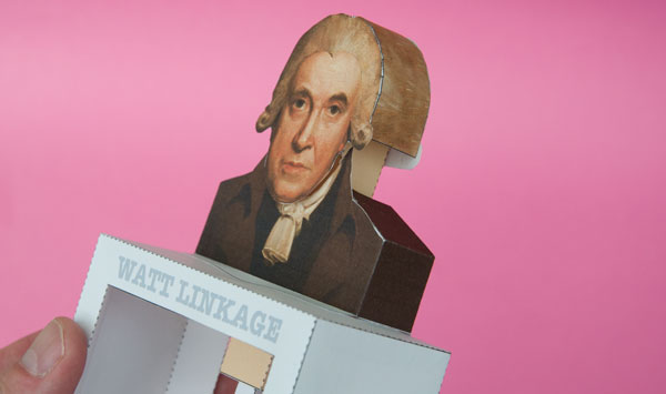
Glue the head to the top of the neck.
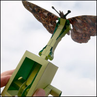
Glue the handle to the rod to complete the model. Once the glue is dry, James Watt’s head can be easily moved up and down but only in a staight line!