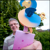

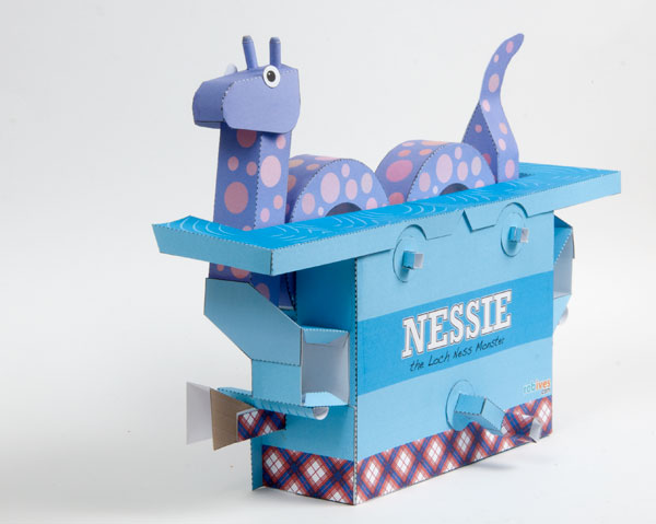
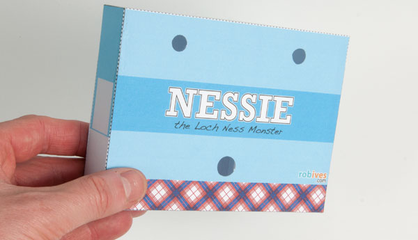
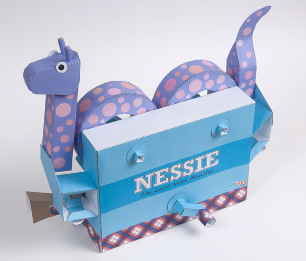
Lurking deep the impenetrable waters of Loch Ness in bonny Scotland lives the mysterious Loch Ness Monster; Nessie, as she is known to her friends. Recreated here is a mechanical version of that fabled beast. Turn the handle and the humps rock and the head and tail bob all powered, of course, via a scotch yoke.
Download the parts and follow along with the illustrated instruction to make your very own mythical beast!
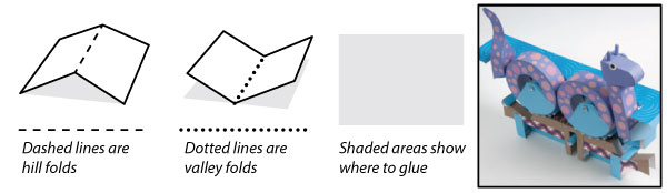
Print out the pages onto thin card (230 micron / 67lb) Score along the dotted and dashed lines before carefully cutting out the pieces.
Crpto-zooological paper project!
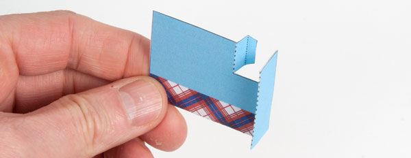
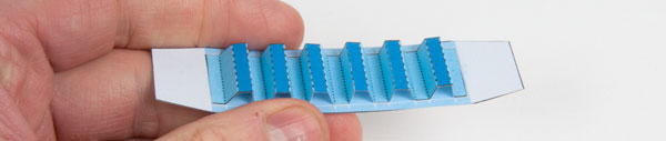
Making the Slider.
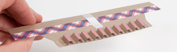
Glue the teeth to the grey areas on the slider. Be as accurate as possible with this to ensure that the rack and pinion works well.
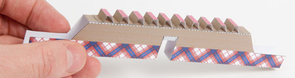
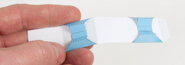
Fold round the slider and glue it together. A chopstick is useful for pressing down the glued edges.
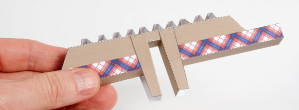
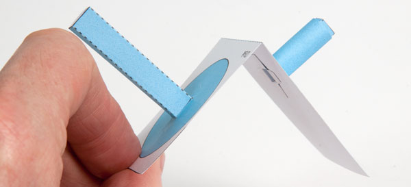
Glue the two yoke sides into place as shown
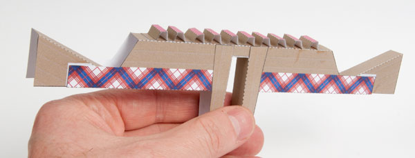
Glue the two cam ends into place using he grey areas for alignment.
Making the Drive Wheel.
Assemble the drive pin by folding round and gluing the main square section tube then rolling round the long tab and gluing it into place.
Assemble the square sectioned drive shaft. Fit the drive shaft and drive pin into the drive wheel.
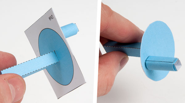
Fold the drive wheel in half and glue it together to make double thickness card. Once the glue is dry carefully cut out the circle.
Assembling the handle.
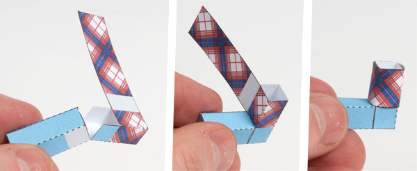
Make the handle in three steps. Fold round and glue the two square section tubes. Fold one tube into the other and glue at ninety degrees. Roll round the long tab and glue it down.
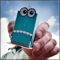
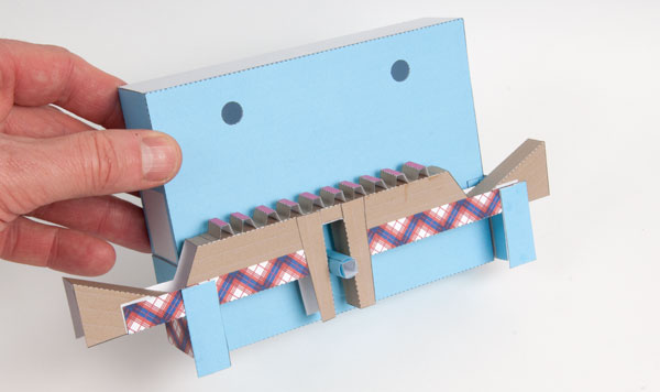
Putting Together the Box.
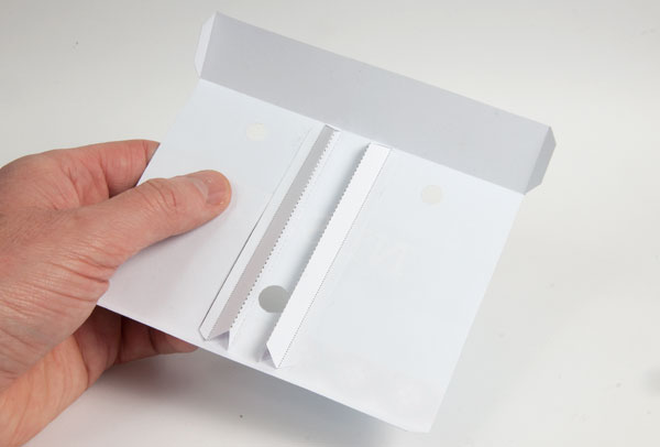
Glue the two box stiffeners up the height of the box so that they are almost, but not quite, touching the centre hole. Repeat this process with the other box side. The box stiffeners give rigidity to the box.
Glue the two box halves together as accurately as possible. Glue on the two ends to close the box.
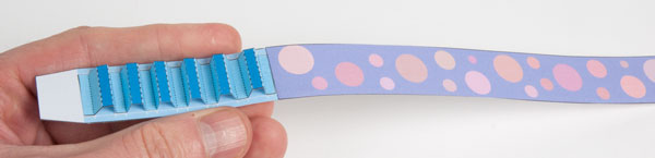
Fold up and make the two slide holders as shown.
Glue the two slide holders to ends of the box. Thread the drive shaft through the holes in the box.
Secure the drive shaft into place with the washer. It should still be free to turn.
Glue the handle to the drive shaft.
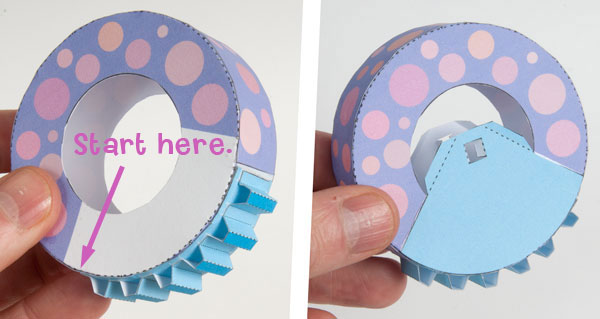
Drop the slide over the drive pin and into the slide holders. Turn the handle to ensure that the slide moves back and forth freely.
Assembling the Hump Wheels
Glue the teeth to the grey areas on the short wheel section. Be as accurate as possible.
Join the two wheel sections together. Line them up with a ruler to ensure that they are straight.
Glue the wheel strip to the wheel sides starting to the side of the first tab and working your way round a few tabs as a time.
Glue the axle pieces into place.
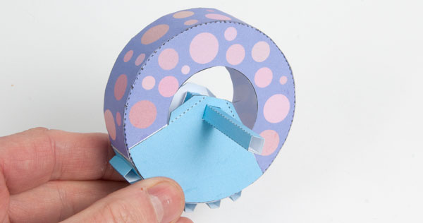
Thread the axle through the square hole and out approx 4mm through the other side then glue it into place.
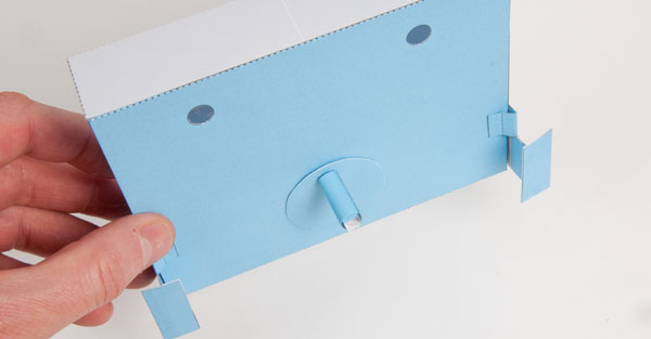
Turn the main handle on the front of the box until the drive pin is at the bottom of its travel and the slide is centred.
Fit the two hump wheels into their holes so that they mesh with the rack and are lined up straight as shown. Secure them with washers on the other side of the box making sure that they are still free to rock back and forth.
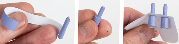
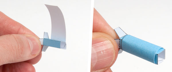
Making the Head.
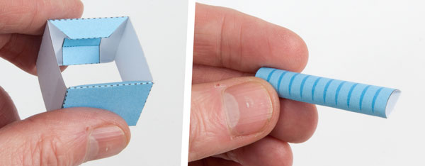
The two horns are made from tightly rolled tubes of paper. Roll the main body of the horns and glue it down. Keep the bottom flat so that the top has a slight curve.
Roll the rest of the long tab round and glue it down to make a step.
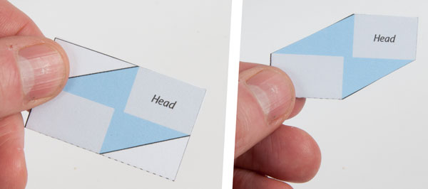
Fit the two horns up through the two holes in the head and glue them into place.
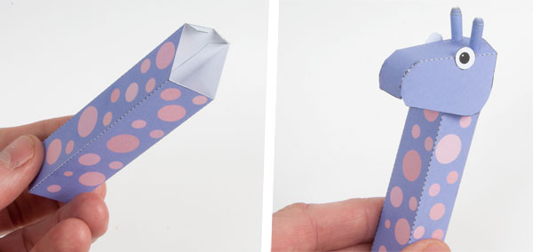
Assemble the neck and glue the head into place
The Cam Followers
In keeping with the Scottish theme I was originally going to use a Watt linkages to move the head and tail.(The Watt linkage was invented by famous Scotsman James Watt.) In the end I decided that the model was already quite complex and these linkages would only add yet more complexity. Perhaps someone would like to give it a try?
The head and tail of this project are powered by cams. Assemble the cam linkages by folding the stiffeners into the middle as shown.
Fold round and glue together the linkage as shown.
The cam follower is a semi-circular tube. roll the card round a pencil to curve it gently before gluing the part together as shown.
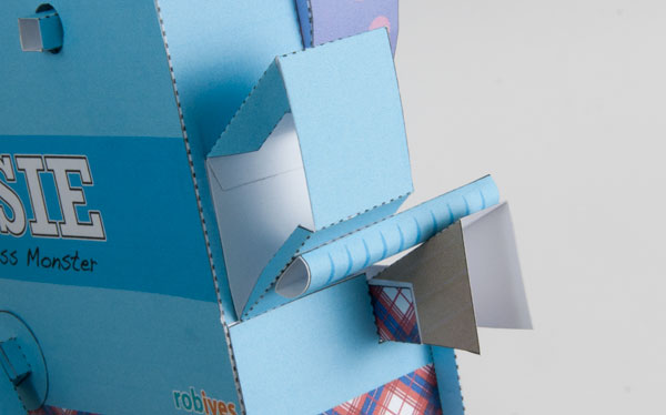
Glue the cam follower linkage to the grey area on the end of the box as shown so that the cam follower rests on the cam surface.
Fold of the head and tail support and glue them to make double thickness card. Once the glue is dry cut away the waste pieces.
Glue the head and fail supports to the cam follower linkages as shown then glue the head and tail into place.
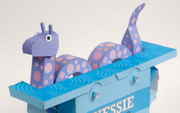
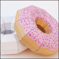
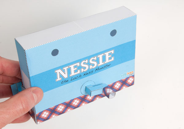
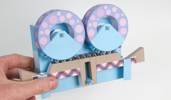
Finish off the project by gluing the two pieces of ripply Loch Ness into place. Turn the handle and Nessie will come to life! The scotch yoke will move the slider back and forth, the rack and pinion will rotate the humps and the cam s will move the head and tail up and down.
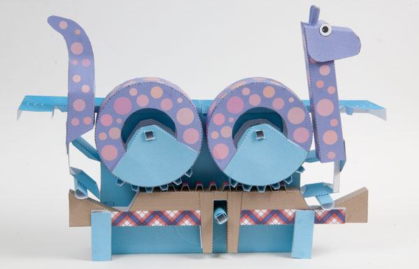
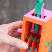
Rear view showing the mechanism. (Always the best bit in my opinion 🙂