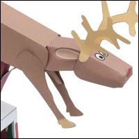

An automata is a character brought to life with a collection of mechanisms. It might be a flying pig or a skiing sheep or perhaps a festive model featuring a moving model of Santa. The common theme is the use of mechanism. In paper automata, the power for the mechanism is usually supplied by a hand turning a crank handle.
The more removed the movement of the automata from the movement of the handle the better the illusion that the character has come to life. If the character bobs up and down exactly in time with the handle on the side of the box then the two movements become connected in the viewer’s mind. If, as an automata designer, you can visually break the link between the handle and the character the viewer will see the model as moving independently. The character comes to life. Gears work well to create this illusion. Turn the handle and because the output movement is slower than the hand the crank takes on its own movement. Just add character!
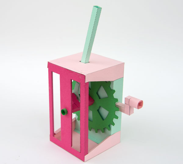
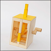
This Essential Mechanisms™ project uses a roughly 2.5:1 reduction gear to drive a crank and pushrod. You need to turn the handle roughly two and a half times for each complete revolution of the crank.
Check out the final result in this YouTube video.
Members can download the parts file for this model for free from the link. Thanks for signing up! Non-members can download the parts for £2.50 and join in the fun.
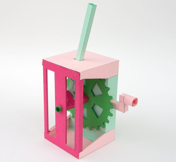
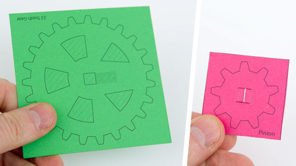
Print out the parts onto four sheets of thin card. 230gsm / 67lb is about right. I’ve printed mine out onto coloured card to make the finished model colourful. You can use white, coloured or patterned card as you please.
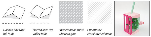
Score along the dotted and dashed lines then cut out the crosshatched areas before carefully cutting out the pieces.
The two gears are made from double thickness card. Fold them over and glue them down.
Once the glue is dry carefully cut them out.
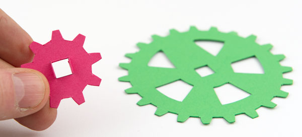
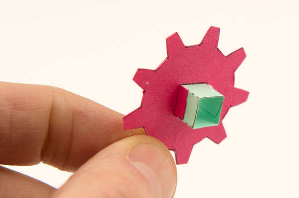
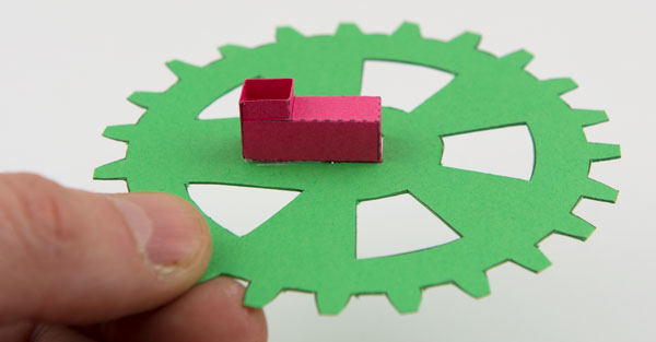
Fit the short axle piece into the pinion gear lining it up with the grey line and gluing down the tabs.
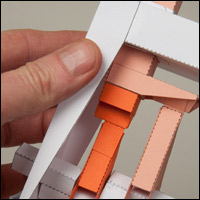
Assemble the two crank pieces as shown in the next to pictures.
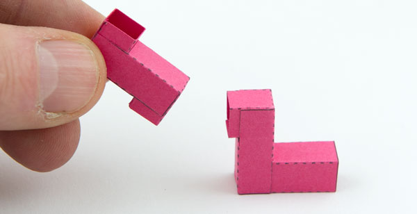
Glue the smaller crank piece into place on the larger gear.
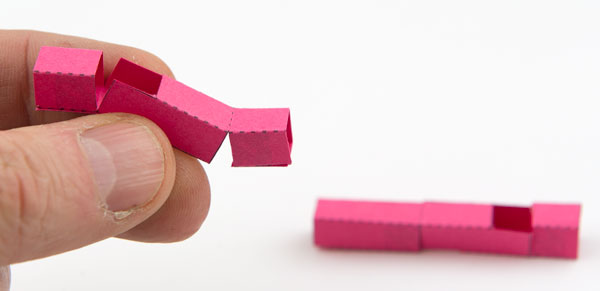
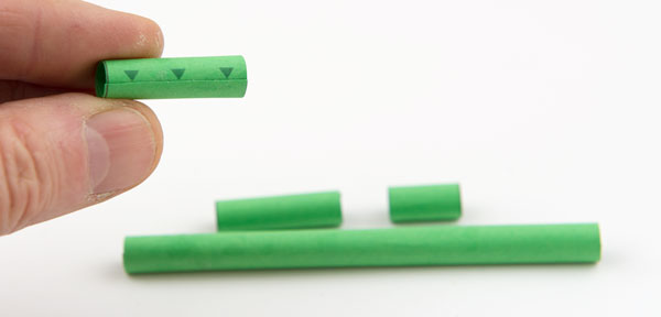
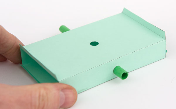
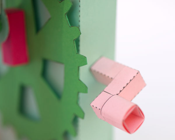
Roll up and glue down the four axle tubes lining up the edges carefully with the arrow points.
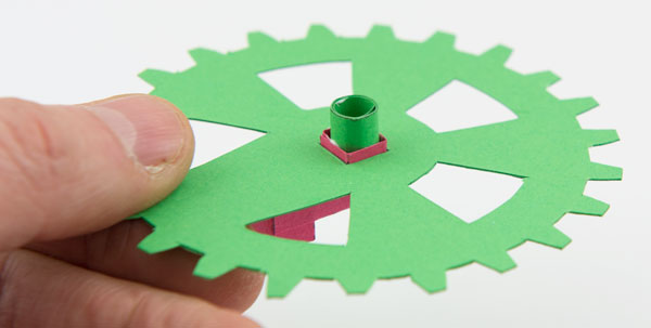
Glue the shortest of the axle tubes into the crank piece on the back of the gear maing a stub axle as shown.
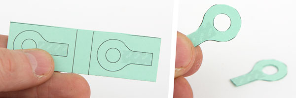
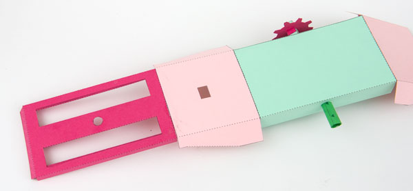
Make up the push rod end pieces from double thickness card as shown. Once the glue is dry carefully cut them out.
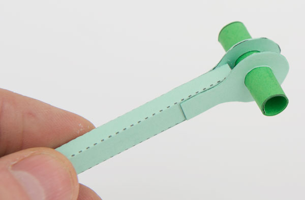
Fit the push rod end pieces onto the end of the push rod. Thread one of the mid length axle tubes into place through the push rod ends. It should be a tight fit but be free to turn.
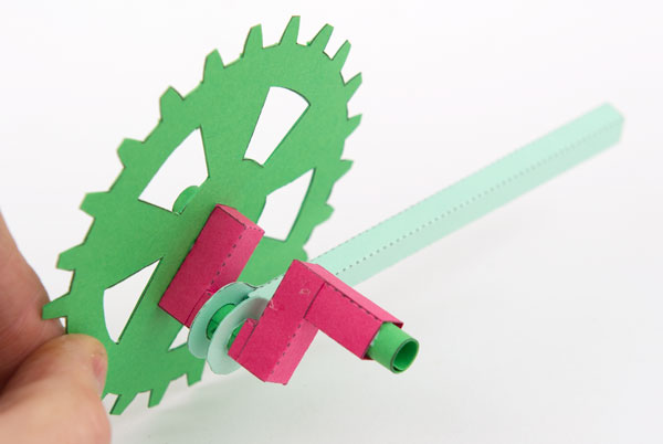
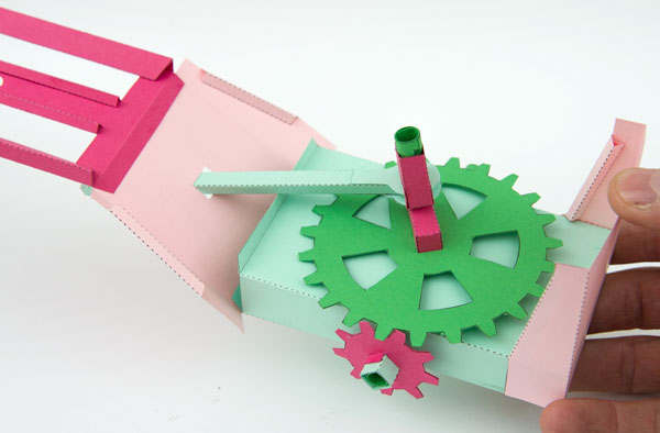
Assemble the gear, crank and push rod as shown using the remaining mid length axle piece.
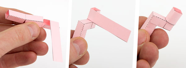
Assemble the handle in three steps as shown.
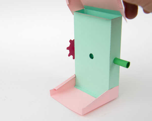
Make up the box back remembering that dotted lines are valley folds so two of the end tabs fold outwards.
Thread the long axle into place in the box back. It should be free to turn.
Fold round and glue down the tabs on the sides of the box top and box bottom to make triangular tubes.
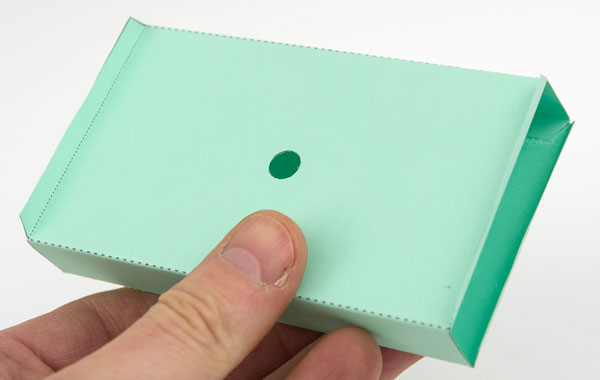
Glue the box top (with the rectangular hole) and the box base (no hole) onto the hill fold tabs on the box back. With the box top to your left fit the pinion gear into place gluing it to the axle.
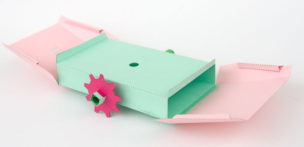
Fold up and glue down the four triangular tubes on the box front before proceeeding. The centre tubes are equilateral triangles, the side tubes are right angled triangles.
Glue the box front to the box top.
Fold up the base and glue it down making as accurate a right angle as possible with the box back.
Thread the push rod up through the hole in the box top. Fit the stub axle of the large gear into the hole in the box back.
Fold round the top and the front fitting it over the axle tube and gluing it to the box base.
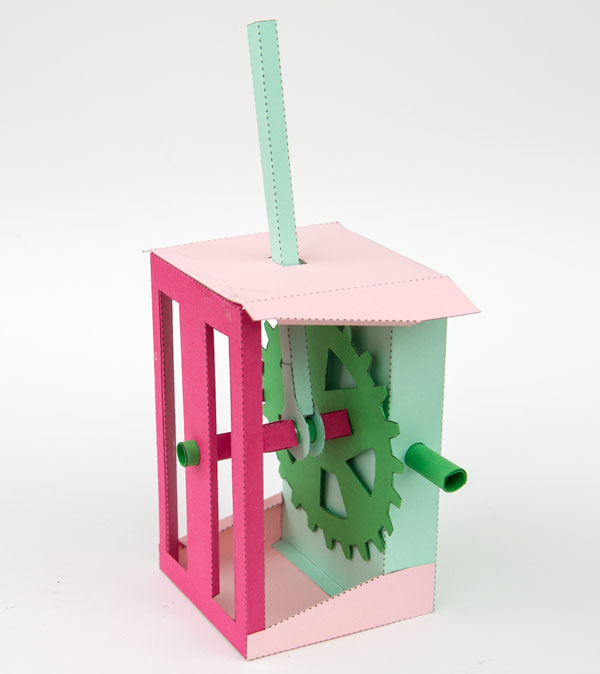
Glue the handle to the axle tube.
Complete the model by gluing the box top flaps down.
Turn the hand and watch the crank turn!