
The crank slider is a mechanism at the heart of many of my paper animation kits. When I’m designing new models I often have to vary the geometry to get the movement that I’m after. This model allows you to change the distance between the crank and the slider to see how the movement is changed. If you are a member you can download the files at the end of this blog post. None members can download the file for a small fee.
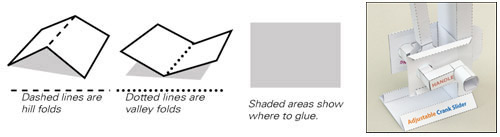
Print the three pages of the parts file onto thin card. I use 230 micron / 230 gram board. Score along the dotted lines and cut out the holes with a sharp knife before you cut out the pieces. Both these jobs are easier on a full sheet. Dotted lines are valley folds, dashed lines are hill folds.
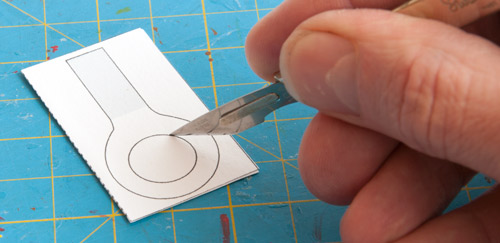
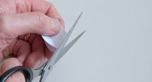
Fold the two crank shaft ends in half and glue them down to make double thickness card. Once the glue is completely dry cut out the hole with a sharp knife then cut out the part with scissors.
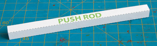
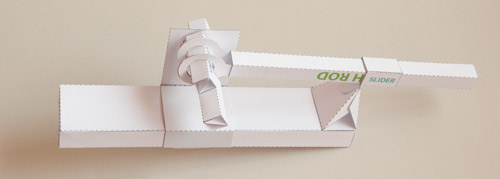
Fold round and glue together the push rod.
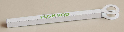
Glue the push rod ends into place on the inside of the push rod as shown. Use the grey areas to ensure that the parts are lined up accurately.
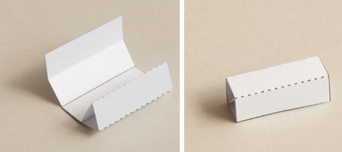
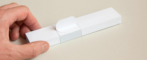
Fold round and glue together the three crank parts in two stages as shown above. The diagonal piece gives the tube strength and rigidity.

Glue one of the crank sides to the crank centre as shown. Don’t glue the other one on yet!
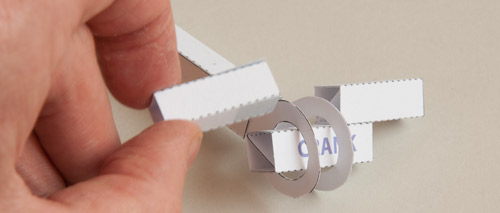
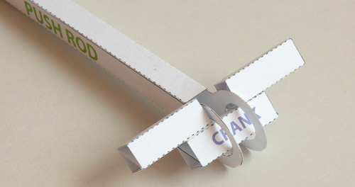
Thread the crank centre through the push rod ends then glue the second crank side into place to complete the crank assembly as shown below.
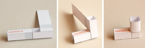
Make the handle in three steps. Fold the tubes up to make square sections.
Fold the two sections, one into the other. Roll the long tab round and glue it down.
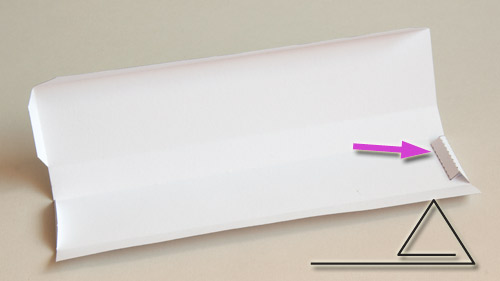
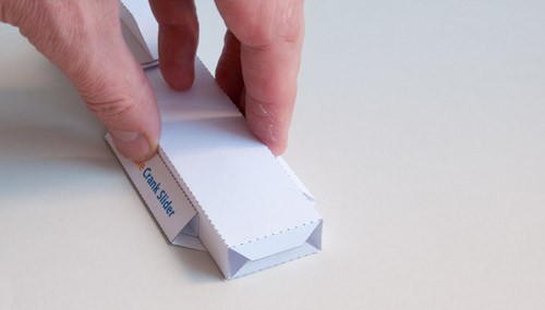
Fold the strengthening tab round on the end of the upright then glue it down. The triangular tube makes the top of the upright more rigid.
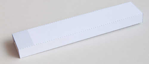
Fold the upright round and glue it together as accurately as possible

Fold round the upright slide and glue it down. Try to be as accurate as possible, the upright slide is only half a millimetre bigger than the upright so accuracy is important here.

Fold the grip in half as shown and glue it together.
Carefully cut round the two grey lines to shape the grip.
Glue the grip to the upright slide in the centre.
Fold up the base to make two triangular section tubes. Hold the upright in position to ensure that the width of the base is accurate but don’t glue it down! You’re just using it as a measure.
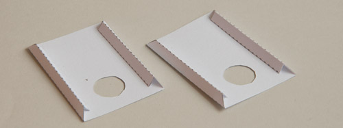
Assemble the two side pieces as shown.

Assemble the slider support and the slider tube then glue them together as shown.
Glue the slider support to the top of the upright on the side opposite the triangular stiffener.
Glue one of the side pieces into place, keep it as accurate as possible.
Thread the push rod through the slider tube then thread one end of the crank into the hole in the side piece.
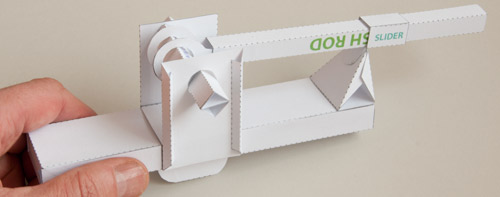
Glue the second side piece into place threading the crank through the hole as you do.
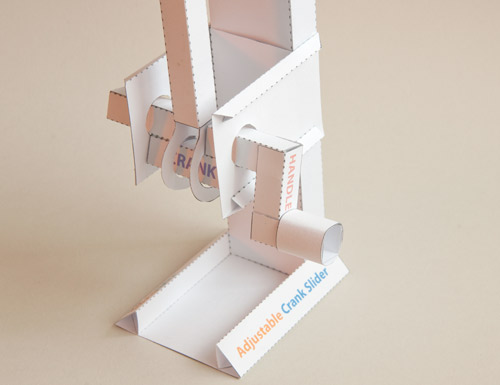
Glue the handle onto the crank then glue the upright to the base to complete the model. Let the glue dry completely before trying it out.
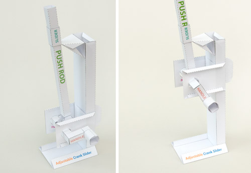
Time to experiment! With the crank assembly as low as it will go, turn the handle and watch how the push rod end moves. Repeat the same process with the crank higher up on the upright, notice how the push rod movement is far more exaggerated. I’ll be posting some animations in the mechanisms section shortly so keep and eye out for them!
USEFUL LINKS:
Paper Mechanisms Multi-Pack – Buy and save!